-
Van Addict

- Rep Power
- 1
91-97 Previa speedometer repair
Not long after I replaced the differential on my van last year, the speedometer started getting sketchy during the course of last summer. Summer 2011 was unusually hot, and after many years of being parked outside, the heat cooked the electronics in the speedometer to death! That wasn't surprising considering that the van is almost 20 years old! At first, the speedometer would read about 10mph off, eventually it got worse and worse till it failed to read higher than 30mph! :o This took the fun out of driving the van and definitely a no go for road trips!
After speaking to my friends who run a garage, they confirmed with me that typically, it's the capacitors on the speedometer circuit board that goes bad. They normally have ones sent out to a specialised speedometer repair shop but their labour isn't exactly cheap! Over the past year, I've been researching and trying to see about just replacing the whole gauge cluster outright with one from Europe since it has a tachometer also. Well, it was a waste of time to say the least. There weren't many to be found, and it was too difficult communicating with the Poles to try to get this to all happen. Then I discovered that, unique to only North America, Toyota changed the harness and connectors in the dashboard since none of these vans here came with tachometers, except for the very rare manual transmission ones the first 3 years the Previa was sold here. :angry: So to even make such a conversion to happen, I would also have to get the connectors with the gauge cluster when buying one from the junk yard somewhere in Europe. Since I don't live there, and I can't really communicate in their language, it wasn't happening. It was either repair mine or buy a replacement from the junk yard, but most of them are in MPH, which doesn't "match" my Canadian spec van... picky aren't I? 
Then a few months ago, I went to the junk yard with my friend and I happened upon a 91 Previa. I decided it was best to practice removing this **** off of one that wasn't mine and one that no one would care if I broke it. After figuring out how to pull the gauge cluster out, I decided to disassemble the thing only to find that it was fairly simple to pull the circuit board off and replace the capacitors, all without risking breakage of the speedometer! It was decided then that I fix this myself instead of paying someone to do it!
It didn't happen right away though, careful research was needed. I talked to another friend who is an electronics guru and he told me he needed to see the circuit board himself so that he could tell me which specific capacitors I needed. Those cell phone pics were crap he said. :mellow: So I went back to the junk yard and just gave myself a five finger discount on the circuit board.  But it didn't end there! A few weeks later, I went to another junk yard and found a 92 Previa, finding out that the circuit board in that one was redesigned and simplified! So I ended up getting that circuit board also, for a nice discount too
So two destroyed speedometers later, I figured out all that I needed and the big wait was coordinating between one of my friends who is better at me in removing interior trim plastics, and with my other friend who has steady hands which I put him to use in soldering the new capacitors.  So it finally happened these past two weeks!
Skipping to disassembling the gauge cluster...
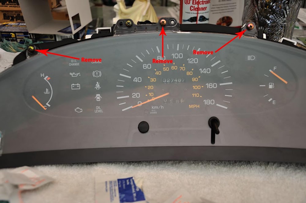
First you needed to remove three screws holding the bezel/lens assembly onto the housing
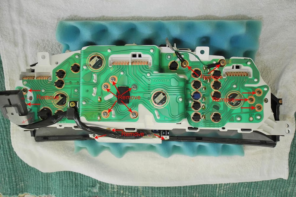
You then need to remove the PRNDL display from the bottom side of the housing. After that, you carefully unclip the black plastic bezel from the housing and pull it apart. It is clipped on tight, so some force is needed! Once that was done, all of the screws holding the gauge cluster on could be removed so that you can pull the assembly off the housing. Note: on the 90/91, you may have already removed it as the PRNDL display is electro-mechanical and is connected to the shifter via a cable. Care must be taken on the 90/91 to disconnect the cable before you pull the PRNDL/gauge cluster out! I don't have a 90/91 so I don't know how it's done
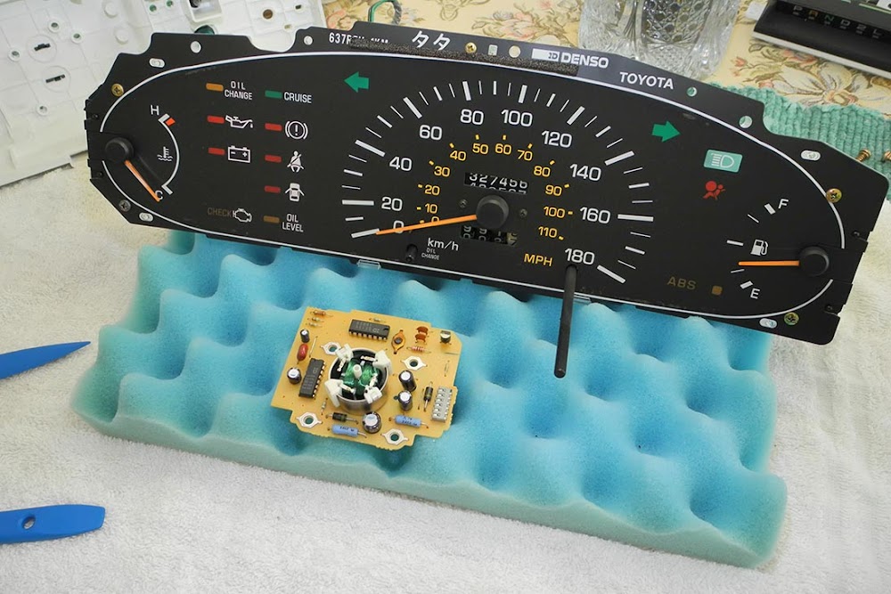
A piece of anti-static foam that comes with computer parts packaging comes in very handy. I saved this all these years and it finally came in handy! 
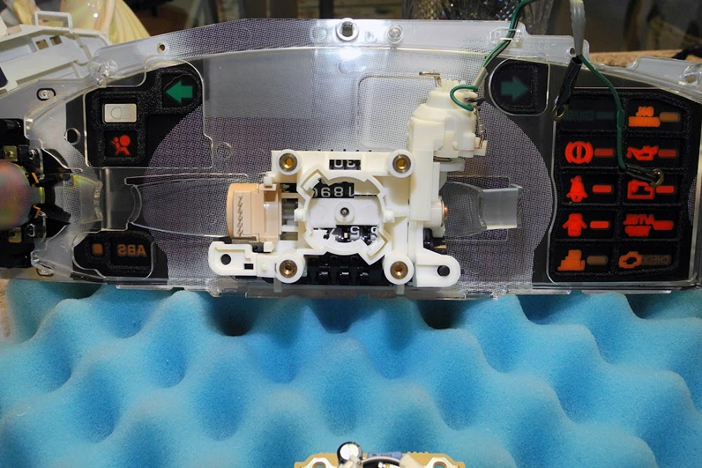
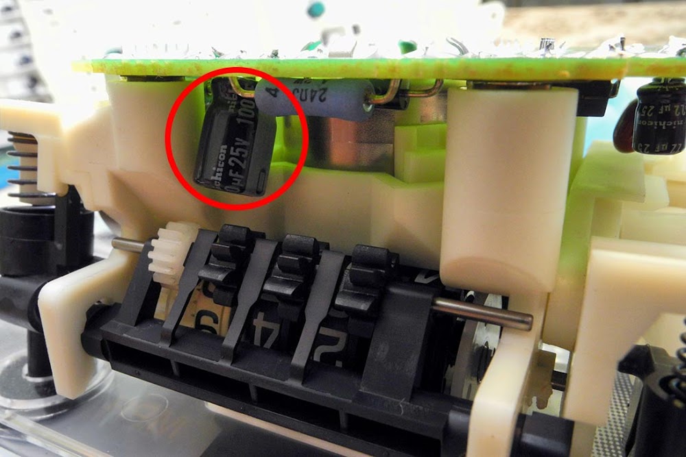
This is how it looks inside:
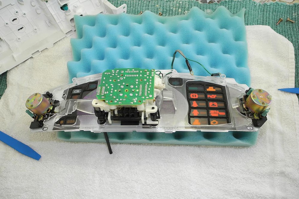
The circuit board just pulls off with a little force
So I went to meet my friend at his apartment and we "setup shop"
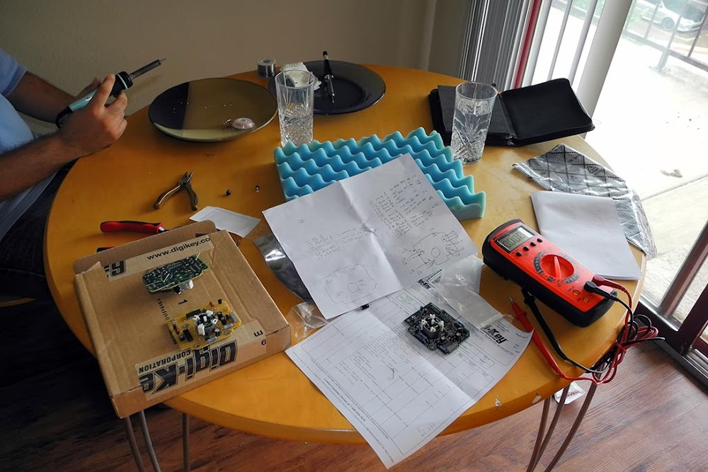
Brand new high quality Nichion and Panasonic capacitors were ordered from Digikey.com all for under $7 to my door!
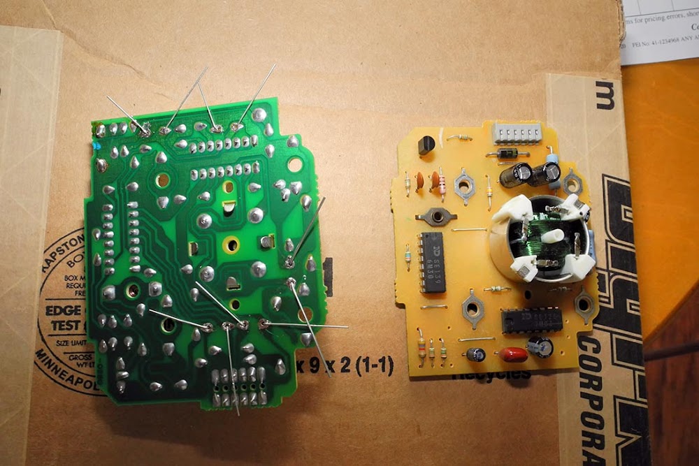
The old capacitors were removed and new ones fitted ready for soldering (circuit board from junk yard on right, shown as reference):
These are the capacitors in question:
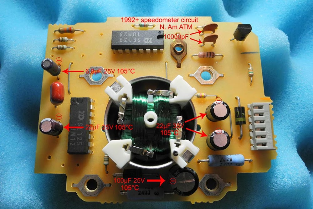
I replaced only the electrolytic capacitors, not the two red 10000pF ceramic capacitors since they normally don't go bad.
One of the new capacitors was so much taller than the original, it ran against the odometer assembly! I managed to bend it out of the way, which allowed it to barely fit! 
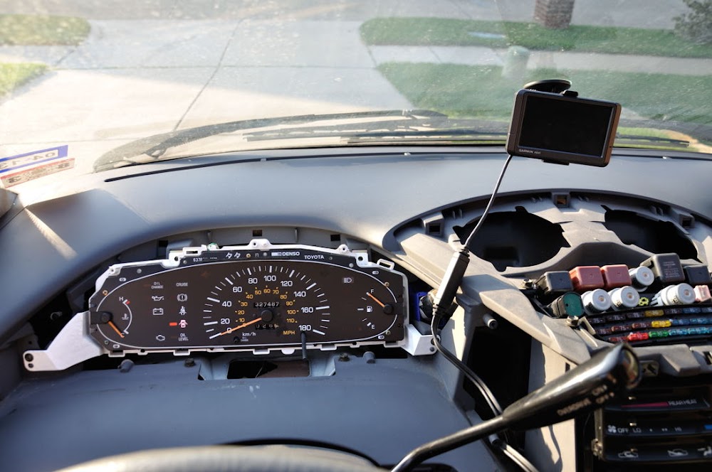
Finally, I replaced all the illumination bulbs, and temporarily fitted it back on the van for testing.
On initial start up, the airbag light came on because I ran the engine without the gauge cluster plugged in a few days before. This is normal. The airbag computer checks to see if the light is working properly. If it detects no light, it will set a code!  Also, the speedometer needle jumped up to 60km/h immediately. I gently pulled the needle off and repositioned it to "0". I got out the GPS and got it ready for some ghetto calibration.
On it's maiden voyage, the speedometer read too fast. So I ended up pulling the needle off and then driving to 100km/h then engaged the cruise control. While I had someone else watch the road, I put the needled back on at 100km/h the best I could. Afterwards, I was happy to see that the speed was within 1km/h difference from the satnav! Close enough for government work! I tested it up to 125km/h and all seemed well. Below 70km/h, the speedometer would read a little slow, but that's no big deal to me. In fact, the speedometer needle was a little shaky below 50km/h, most probably because these new components aren't original, but I don't really care. The speedometer needle also didn't start moving till I was really going 20km/h. Again, I don't care. For $7, it was a fantastic repair and I would do it again in a heartbeat! I'm pretty sure I saved more than $100!
Oh and before I put this back together, I decided to just get an aftermarket tachometer. It's cheaper and easier than trying to go with the European spec gauge cluster.
See here:
http://www.teoc.ws/community/topic/4...ometer-fitted/
-
Van Addict
- Rep Power
- 1
Re: 90-99 Previa speedometer repair
Just a note to all... AVOID having no gauges connected to the bus if you are going to move it around the driveway! It will freak out the airbag computer and set a fault code! It is NO FUN clearing the code!
Thanks to this guide I did it, but not after a few attempts! 
http://www.toyotapart.com/CLEARING_S...T-EL017-90.pdf
Anyway, the 90/91 circuit board looks like this:

-
Re: 90-99 Previa speedometer repair
Thank you for this informative write-up  .
.
-
Forum Newbie
- Rep Power
- 0
Re: 90-99 Previa speedometer repair
I wanted to add my experience in replacing the capacitors in my 1995 USA model Previa SC. The speedometer would work consistently, but would read low. As much as 20mph on the highway. I suspected bad capacitors.
While most of the repair went as described above, there were some differences that I wanted to make note of in case they could help others.
I waited to order replacement capacitors until I had pulled out my "Combination Meter" to access the speedometer board. Before taking the combination meter apart, I took a moment to access the performance of the needle. It could be moved easily by my finger and would return to zero with a smooth, clearly damped motion. I hadn't done additional research at this time and didn't realize that I could have lifted the needle over the stop post and let it settle into a position dictated by its spring to give me a reference point for reassembly which could have perhaps negated the need for the driving recalibration of the unit. It seems most other similar speedometer needles want to move to about 5 o'clock after being lifted over the stop pin.
Removal of the meter board was fairly straightforward. It wasn't clear just from looking that there are two plastic clips on the inside of the needle actuator frame that are holding it place. While it's not possible to really unclip them, using a small flat blade screwdriver to pry on them a bit will get them loosened up a bit and make removal of the board easier. The electrical connector for the odometer motor can also be pried on a bit to get it started.
Examining the capacitors showed that all the values are the same as the ones shown in the 1992+ board photo in the original post, however the pair of 22µf 35v capacitors on my 1995 board are slightly different. They are Non Polarized which means there are not + and - terminals. A regular polarized cap might work for a while, but it seems the engineers found a reason to spec the non-polarized ones, Digikey.com had them, though the choices were fewer. I tried to spec caps that had the longest life at 105°C to make sure I was less likely to have to do this again. So I chose 2000 hours vs 1000 hours when possible. All the caps are 20% tolerance. I was hoping to spec a tighter tolerance, 10% or even 1%, in case it made a difference to the accuracy of the speedometer, but while they were listed, virtually none were in stock and the lead times were very long.
Testing the caps I took out, only the 6.8µf cap was bad. I saw a video of a similar Denso speedo repair where the man said the 6.8 was the bad one on his speedo too. It would have been possible for me to replace just the 6.8µf cap without removing the board, but I felt replacing them all was the better repair. However, pulling the board off resulted in a problem that took several hours to figure out.
I replaced the caps without any issue, but after putting the board back on, the needle was stiff and didn't want to move easily. It would stay where it was placed and could be moved but with way more force than before the repair. Removing the board and examining the needle and the odd intermediate shaft that the Previa has between the needle and the actuator (most Denso speedos I've seen have the needle attached directly to the actuator) showed that there was no issue with the needle, the return spring or the intermediate shaft itself. The shaft would rotate freely and indeed had quite a lot of play in all dimensions. The actuator is a bit of a black box, er green box, as there's just a white tube that sticks up in the middle of the green wire windings. Clearly it has some sort of silicon grease in there to act as the damping agent as that was seen on the end of the intermediate shaft. If it move the board close enough to the actuator to engage the shaft, it would properly dampen the needle movement, but not smoothly has I was holding the board in one hand while moving the needle with the other. Hmm. I did find that if I pushed the board all the way in and held the board in my right hand, vertically, with the faceplate off the table, while moving the needle with my left hand, I could get it to move in the proper damped fashion while returning to zero. So I thought that perhaps something had happened inside the actuator during the repair and maybe spacing the board out with some washers would find a happy location where things would work. The trick here is that the screws are actually acting as electrical contacts, bringing electricity from the flexible circuit board on the back of the combination meter into the speedo board so the spacers would have to be metal washers and to keep them in place while putting the faceplate/board w washers combination required the use of Q-Tips put into the screw holes to location the washers while put the rear housing over the board. Then with the board horizontal, the Q-Tips could be pulled out one by one and replaced with the screws, one by one. Great. Washers installed. But it didn't help. The needle was still binding up. I tried two washers to see if more spacing helped. Nope. Grrr.
I went away and did some research on replacement speedos or new GPS speedometers. There are very few 1995 Previa in the breaker yards now. There's one in Houston and two in Calfornia, but I didn't search the entire country. There's a dumpy '92 with no title in Georgia for $500 on Craigslist, but that's the wrong speedo. (Wrong board and doesn't have the same rear end as my SC)
Coming back to the table, it occurred to me that I was getting proper needle operation when I was holding the board with one hand. Why? Ah, the torque of the faceplate weight was pulling the board away from the top two white plastic pegs while the bottom two pegs were in full contact with the board. It seemed the the needle shaft was binding up because of a misalignment of the axis of two components. I put it back together with one washer for each of the top two pegs and proper operation was restored. Yipee. I put in into the dash and did the driving calibration and am happy with it reading just a couple of mph high. Thinking about the specifics of the original issue, it's possible that the speedo was reading low because of extra drag from the misalignment and that taking things apart let thing spring into a more relaxed, but even more misaligned place and the dead capacitor was a secondary finding. I'll never know just what happened, but hopefully this may save someone some hair pulling moments.
Here's a photo of the first attempt with spacers for each bolt, not just the upper two. Note that one of the white plastic latches that holds the actuator in position is visible.
Previa Speedo board spacers.jpg
Last edited by isights; 09-25-2022 at 12:20 PM.
Tags for this Thread
 Posting Permissions
- You may not post new threads
- You may not post replies
- You may not post attachments
- You may not edit your posts
-
Forum Rules


 Reply With Quote
