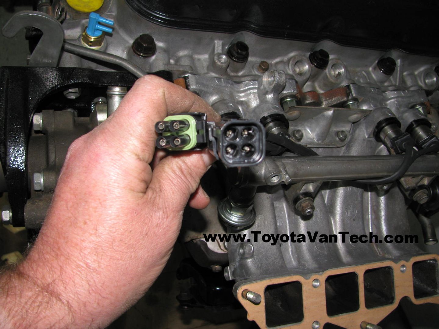
If you're good with your hands you'll figure it out. In the quote below (which I'm sure you've seen) I hid links in the text. The tools you need, the connectors, wires, everything. Get a few extra pins and experiment until you're satisfied with the quality of your crimps. After you've completed the new harness you'll need to cut your old one and put matching connectors on the existing harness wires. Before you do that, you'll want to strip off all the old tape/covering so you can trace back and identify the wires. You'll want to be sure to identify and mark before you cut because some of the wires are the same color. If you go back far enough you will likely find some of the injector wires branch from common harness wires. If that happens just leave the old splices and put the Weather Packs on about 2" or 3" after the common splices (just makes your job easier). Tim

Quote Originally Posted by timsrv View Post
One thing that always annoyed me with the van is the requirement to remove the top half of the intake manifold just to connect/disconnect the engine wire harness to the fuel injectors. The last time I did this I cut the injector part of the harness off & built a removable injector harness (it worked great). This makes it possible to completely assemble the engine before installation. I liked it so much I built a removable harness for this one too (old connectors were shot anyhow). I'm using Standard part #S697 Bosch style injector connectors w/wire and 4 PIN SQ 16-14 AWG Weatherpack connectors. I use 16 AWG automotive primary stranded wire to go from the injector connectors to the Weatherpack connectors. I solder & shrink tube the connections to each injector connector wire, then cover the assembled harness with more shrink tubing. Note: Special crimpers are required for the Weatherpack connectors. If you work with these type connectors (also used on GM) I highly recommend having a Delphi Packard Weatherpack Terminal Release Tool in case you need to pull pins back out. Here is the finished harness:


Male connector positions A&B power injector #1 & positions C&D power injector #2. Female connector positions D&C power injector #3 & positions B&A power injector #4.